Scene controls
Cutting Planes
Multiple cutting planes can be configured to visualise Scene sections in any plane.
Cutting planes are defined on the Cutting Planes tab of the scene Site Settings panel. Multiple cutting planes can be drawn. Click and drag the cutting plane to adjust its position.
| Control | Description |
|---|---|
|
Elevation Filter |
Toggle to enable or disable the elevation filter (Scene slicer). The filter creates two horizontal planes and filters all elements in the scene above and below the planes. The plane elevation can be set from the properties panel or from the filter slider to the right of the 3D Scene. |
| Cutting Planes | Enables or disables any cutting planes in the scene. |
| Create Cutting Plane | When Cutting Planes are enabled, clicking this icon will allow the cursor to create cutting planes when click-dragging in the scene. The icon changes to a grey background when it is active. |
| Show Cutting Planes |
Toggle visibility of the cutting planes. Cutting planes appear as grey semi-transparent planes in the scene. Click-drag on the visible plane to move the cutting plane perpendicular to its orientation. |
| Clear Cutting Planes | Remove all cutting planes from the scene. |
Vertical scene slicer
The scene can be filtered in the Z dimension by applying the vertical slicing tool on the right of the 3D Scene. Click in the 3D Workspace then press E to toggle the vertical slicer bar. The slider can also be accessed from Site Settings > Cutting Planes tab > Elevation Filter icon.
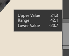
The upper and lower extents can be set by adjusting the grab handles. Once a range is set, it can be scrolled by clicking the middle section and moving it up or down.
The upper and lower elevation and elevation range of the Scene Slicer can also be set with numeric values from the cutting planes tab of the Properties panel.
Block Model filter
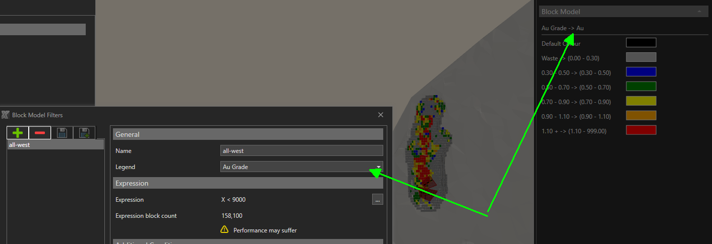
Blocks from the block models can be visualised in the Scene by configuring a filter under Site settings > General > Block Model Files > Filter and click the Ellipsis button.
| Control | Description |
|---|---|
| Name | The name of the block filter. |
| Legend |
The legend to use for the blocks. |
| Expression | An expression that returns true or false based on the properties of the blocks. Blocks that return true will be visible. |
| Expression block count | The count of blocks that return true from the Expression. |
| Exclude blocks outside pit limits | Option to exclude blocks from outside pit limits. |
| Exclude blocks above topography. | Option to exclude blocks from above the topography surface. |
| Actual block count | The calculated block count with expression and options applied. |
To visualise the blocks for the selected filter dropdown click the eye of the Filter property or toggle with Ctrl+B.
Blocks will not be visible until the block model cache files have been downloaded from the server to the users' XECUTE cache folder.
Legends
To show an overview of the applied legends in the scene, click the Legends tab at the right edge of the scene window.
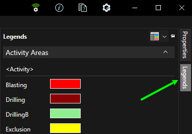
To control the visibility of the legend overviews in the Legends panel, click the Legend icon then select the legend names in the list to make them visible. Legends are only selectable if there are items in the scene that use the legend.
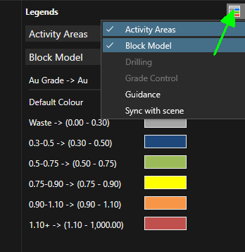
The Sync with scene legend list entry will hide any legend items that are not currently displayed in the 3D scene. This keeps the legend uncluttered.
Block visibility
Blocks from the block models can be visualised in the Scene by configuring a filter under Site Settings > General > Block Model Files > Filterand click the ellipsis button.
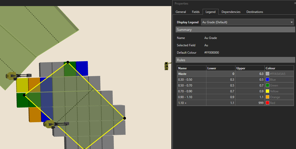
The legend applied to the blocks is set in the block filter configuration General section.
Use Ctrl+B to toggle the visibility of the blocks in the active filter.
Block will not be visible until the block model cache files have been downloaded from the server to the users XECUTE cache folder.
Activity area blocks
To view the blocks of selected activity areas, click the BLOCK scene menu item or press the B key to toggle through the view options.
The default legend used for the activity is set in XECUTE Config and can be overridden for the selected activity areas from the properties panel.
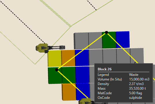
With the activity areas selected, press the W key to switch to outline mode so that the blocks are more visible, and their details appear in the mouse tooltip as shown below.
Vertical Exaggeration
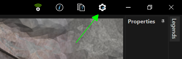
The items in the 3D Scene are, by default, rendered with a vertical scale factor of 1. To adjust the factor enter a new value in 3D Workspace Graphics Setting > 3D Settings > Vertical Exaggeration. The Graphics Settings control is in the top right of the screen.